![](https://static.wixstatic.com/media/5afe60462baf41e79586f3fdaf78d664.jpg/v1/fill/w_1920,h_1164,al_c,q_90,usm_0.66_1.00_0.01,enc_avif,quality_auto/5afe60462baf41e79586f3fdaf78d664.jpg)
Armless Crutch
ENGS 021: Introduction to Engineering // Professor Ian Baker
Team: Brian McLaughlin, Martin Anguita, Nolan Kasper, Rebecca Nova
Project Objective
The objective of the course was to develop a solution to a problem currently impacting society during the nine week trimester. I was the project manager throughout the life of the project and established critical milestones, timelines, and lines of communication between team members and advisors. I was also the lead mechanical engineer developing the 3D SolidWorks model and fabricating prototype and final product components in Thayer's machine shop.
Problem
Society is in need of a device that provides individuals with lower leg injuries the mobility they enjoyed when uninjured.
Identified User
Injured, active, young adults who have recently sustained a lower-leg injury
Solution
An "arm-less" crutch that attaches to the users thigh and allows for movement without the use of his or her upper limbs.
![](https://static.wixstatic.com/media/785403_9e78adb3cf034427871f8c3cddbd3745~mv2_d_1920_1483_s_2.jpg/v1/crop/x_636,y_0,w_696,h_1483/fill/w_238,h_507,al_c,q_80,usm_0.66_1.00_0.01,enc_avif,quality_auto/785403_9e78adb3cf034427871f8c3cddbd3745~mv2_d_1920_1483_s_2.jpg)
![](https://static.wixstatic.com/media/785403_695a2af443894efe95200592ae57124d~mv2_d_2448_3264_s_4_2.jpg/v1/crop/x_159,y_139,w_1632,h_3125/fill/w_264,h_507,al_c,q_80,usm_0.66_1.00_0.01,enc_avif,quality_auto/785403_695a2af443894efe95200592ae57124d~mv2_d_2448_3264_s_4_2.jpg)
Design Development
Once a problem had been identified, potential solutions were evaluated and compared in a requirement matrix. Requirements were determined through surveys of the intended user at Dartmouth College and through communication with physicians who typically prescribe crutches. The requirements whose importance was heavily emphasized by users and physicians were given increased weights against other requirements in the comparison matrix below.
![](https://static.wixstatic.com/media/785403_6663451f29984e5ba1318e1245644c3d~mv2.png/v1/fill/w_688,h_231,al_c,q_85,usm_0.66_1.00_0.01,enc_avif,quality_auto/785403_6663451f29984e5ba1318e1245644c3d~mv2.png)
Figure 1 - Solution comparison matrix. The armless crutch method proved to be the best solution when compared to potential alternatives. The "arm crutch" refers to the standard state-of-the-art crutches.
![](https://static.wixstatic.com/media/785403_c42aaf2c0ac944e1ba5b6d8c15714d7e~mv2.png/v1/fill/w_708,h_264,al_c,q_85,usm_0.66_1.00_0.01,enc_avif,quality_auto/785403_c42aaf2c0ac944e1ba5b6d8c15714d7e~mv2.png)
Figure 2 - Specification matrix. Once the armless crutch was determined to be the solution that best fit the product requirements, specifications were established to aid in the development of a final design. For the first two requirements, the time taken to complete each task with conventional crutches was used as a baseline
![](https://static.wixstatic.com/media/785403_8d320299a1f54deda000f9a6a168aa65~mv2_d_1239_1754_s_2.jpg/v1/crop/x_0,y_109,w_1194,h_1515/fill/w_297,h_377,al_c,q_80,usm_0.66_1.00_0.01,enc_avif,quality_auto/785403_8d320299a1f54deda000f9a6a168aa65~mv2_d_1239_1754_s_2.jpg)
![](https://static.wixstatic.com/media/785403_e00621c764ce41979cb2ef7469ddea10~mv2_d_1239_1754_s_2.jpg/v1/fill/w_267,h_378,al_c,q_80,usm_0.66_1.00_0.01,enc_avif,quality_auto/785403_e00621c764ce41979cb2ef7469ddea10~mv2_d_1239_1754_s_2.jpg)
Figure 3 - A sampling of the sketches used to aid group discussion in establishing an initial design
Prototype Development
After determining a tentative design for the armless crutch, prototypes were developed to refine the product into a solution that met the needs of the final user.
![](https://static.wixstatic.com/media/785403_6d11066c9ef54809a2a5a57d09cddd9f~mv2_d_2448_3264_s_4_2.jpg/v1/crop/x_486,y_131,w_1261,h_3068/fill/w_224,h_545,al_c,q_80,usm_0.66_1.00_0.01,enc_avif,quality_auto/785403_6d11066c9ef54809a2a5a57d09cddd9f~mv2_d_2448_3264_s_4_2.jpg)
![](https://static.wixstatic.com/media/785403_9cdc7310624f44508bc922340406ec67~mv2_d_2448_3264_s_4_2.jpg/v1/crop/x_233,y_257,w_1730,h_3007/fill/w_315,h_548,al_c,q_80,usm_0.66_1.00_0.01,enc_avif,quality_auto/785403_9cdc7310624f44508bc922340406ec67~mv2_d_2448_3264_s_4_2.jpg)
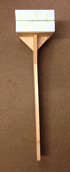
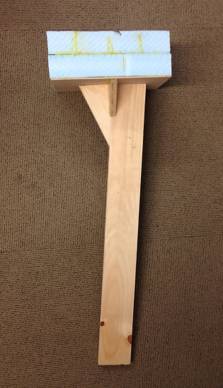
Figure 4 - Initial "works-like" prototype. The user holds the device to the bottom of their thigh and takes steps as normal. This prototype provided feedback on the hight of the crutch, the foot design, and a means to gather very preliminary user feedback
![](https://static.wixstatic.com/media/785403_e5152b0df16d409896c3571c4d955f08~mv2.png/v1/fill/w_298,h_380,al_c,q_85,usm_0.66_1.00_0.01,enc_avif,quality_auto/785403_e5152b0df16d409896c3571c4d955f08~mv2.png)
![](https://static.wixstatic.com/media/785403_65418a176cfd45c48d397c071f51b700~mv2_d_2448_3264_s_4_2.jpg/v1/fill/w_286,h_381,al_c,q_80,usm_0.66_1.00_0.01,enc_avif,quality_auto/785403_65418a176cfd45c48d397c071f51b700~mv2_d_2448_3264_s_4_2.jpg)
![](https://static.wixstatic.com/media/785403_c3766e31686344a19061026a23b33fe6~mv2_d_2448_3264_s_4_2.jpg/v1/fill/w_287,h_382,al_c,q_80,usm_0.66_1.00_0.01,enc_avif,quality_auto/785403_c3766e31686344a19061026a23b33fe6~mv2_d_2448_3264_s_4_2.jpg)
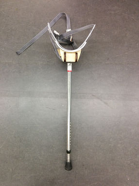
Figure 5 - A second "works-like" prototype. This prototype was used for user testing and to verify the design against the solution specifications above. The leg height, straps, leg location, and foot typer were all adjustable to best refine the product into it's final form
Figure 6 - The videos above show a sampling of user testing. The left shows a user climbing stairs with conventional under-arm crutches and after the prototype crutch, and the right video shows the user carrying plates with fore-arm crutches similar to conventional crutches and with the prototype crutch
Component Testing
Elements of the final solution were prototyped and used to gather feedback from users. These include the foot design and the strapping mechanism.
![](https://static.wixstatic.com/media/785403_9f75639dbd1b4215b1197d6139d99352~mv2_d_2448_3264_s_4_2.jpg/v1/crop/x_209,y_363,w_2043,h_2364/fill/w_293,h_339,al_c,q_80,usm_0.66_1.00_0.01,enc_avif,quality_auto/785403_9f75639dbd1b4215b1197d6139d99352~mv2_d_2448_3264_s_4_2.jpg)
![](https://static.wixstatic.com/media/785403_f374fddaec4a4172b0d1ec6dc8498599~mv2_d_3264_2448_s_4_2.jpg/v1/crop/x_0,y_783,w_3264,h_1142/fill/w_489,h_171,al_c,q_80,usm_0.66_1.00_0.01,enc_avif,quality_auto/785403_f374fddaec4a4172b0d1ec6dc8498599~mv2_d_3264_2448_s_4_2.jpg)
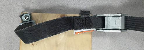
Figure 7 - Boards used to test strapping mechanisms. After user feedback on ease of use, a combination of a velcro and clipping mechanism would be implemented in the final design. The cinching method used in the second "works-like" prototype proved to be too cumbersome
![](https://static.wixstatic.com/media/785403_f9fa8c6b475c422d855befcea7c94c25~mv2_d_3264_2448_s_4_2.jpg/v1/fill/w_377,h_283,al_c,q_80,usm_0.66_1.00_0.01,enc_avif,quality_auto/785403_f9fa8c6b475c422d855befcea7c94c25~mv2_d_3264_2448_s_4_2.jpg)
![](https://static.wixstatic.com/media/785403_ea14ed383cac44bc809e69f453c68ba5~mv2.png/v1/fill/w_335,h_278,al_c,q_85,usm_0.66_1.00_0.01,enc_avif,quality_auto/785403_ea14ed383cac44bc809e69f453c68ba5~mv2.png)
Figure 8 - Foot "works-like" prototypes. Wood and rubber were used to construct the prototypes. Each was designed to give the user additional stability and a combination of the two was implemented in the final design
Final Design and Fabrication
Based on the results obtained from user testing with all prototypes a final prototype was developed using fiberglass and carbon fiber layups, a 3D printed foot, velcro straps that clip on and off and cinch tight with a rotary dial (modified from those used on a knee brace), and an adjustable aluminum base.
Cradle
![](https://static.wixstatic.com/media/785403_d3dfad5c973c46d8831a7631d8b3d033~mv2_d_3264_2448_s_4_2.jpg/v1/crop/x_0,y_85,w_3264,h_2316/fill/w_420,h_298,al_c,q_80,usm_0.66_1.00_0.01,enc_avif,quality_auto/785403_d3dfad5c973c46d8831a7631d8b3d033~mv2_d_3264_2448_s_4_2.jpg)
![](https://static.wixstatic.com/media/785403_9cd6521128d14175ae74541c9cdb05b5~mv2_d_3264_2448_s_4_2.jpg/v1/fill/w_398,h_299,al_c,q_80,usm_0.66_1.00_0.01,enc_avif,quality_auto/785403_9cd6521128d14175ae74541c9cdb05b5~mv2_d_3264_2448_s_4_2.jpg)
![](https://static.wixstatic.com/media/785403_a10a776bd3ff42829560395bee67a7b9~mv2_d_3264_2448_s_4_2.jpg/v1/crop/x_0,y_277,w_3030,h_1773/fill/w_467,h_273,al_c,q_80,usm_0.66_1.00_0.01,enc_avif,quality_auto/785403_a10a776bd3ff42829560395bee67a7b9~mv2_d_3264_2448_s_4_2.jpg)
Figure 9 - Crutch cradle construction. The cradle was constructed of a laser-cut plywood spine attached with epoxied cotton fibre to a fiberglass mold. A carbon fiber cylinder was then fitted onto the spine and a carbon fiber layup was then laid over the assembly to provide rigidity. Black foam was then used to fill the area in contact with the user
Strapping Mechanism
![](https://static.wixstatic.com/media/785403_57a536e11ad9439eb0887c597071b6e8~mv2_d_3264_2448_s_4_2.jpg/v1/fill/w_409,h_307,al_c,q_80,usm_0.66_1.00_0.01,enc_avif,quality_auto/785403_57a536e11ad9439eb0887c597071b6e8~mv2_d_3264_2448_s_4_2.jpg)
![](https://static.wixstatic.com/media/785403_4e4c5078c0f64e26aa1c871d477ca668~mv2_d_3264_2448_s_4_2.jpg/v1/fill/w_409,h_307,al_c,q_80,usm_0.66_1.00_0.01,enc_avif,quality_auto/785403_4e4c5078c0f64e26aa1c871d477ca668~mv2_d_3264_2448_s_4_2.jpg)
![](https://static.wixstatic.com/media/785403_99ef1ef2b2114691976c07ff215e8dc3~mv2_d_3264_2448_s_4_2.jpg/v1/fill/w_417,h_313,al_c,q_80,usm_0.66_1.00_0.01,enc_avif,quality_auto/785403_99ef1ef2b2114691976c07ff215e8dc3~mv2_d_3264_2448_s_4_2.jpg)
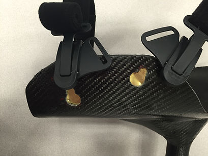
Figure 10 - Final strapping mechanism. The final strapping method, modified from the straps of a knee brace, consists of two clips that insert into the side of the cradle and lock into place. Circular dials, shown in the bottom picture, were used to cinch the strap to the desired tightness. The straps used velcro so they could be lengthened or shortened as needed
Foot and Lower Leg
![](https://static.wixstatic.com/media/785403_8e3aa5a735c94af6ae57f0fb3fffe87b~mv2_d_1920_1483_s_2.jpg/v1/crop/x_553,y_0,w_834,h_1483/fill/w_261,h_464,al_c,q_80,usm_0.66_1.00_0.01,enc_avif,quality_auto/785403_8e3aa5a735c94af6ae57f0fb3fffe87b~mv2_d_1920_1483_s_2.jpg)
![](https://static.wixstatic.com/media/785403_7971788754f742b3b7bfd76b31e8d787~mv2_d_2448_3264_s_4_2.jpg/v1/crop/x_256,y_0,w_1875,h_3264/fill/w_265,h_461,al_c,q_80,usm_0.66_1.00_0.01,enc_avif,quality_auto/785403_7971788754f742b3b7bfd76b31e8d787~mv2_d_2448_3264_s_4_2.jpg)
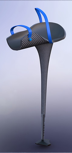
Figure 11 - Final 3D model (left) and physical prototype (right) of the the foot assembly. The 3D printed final foot had a curved bottom and extended features for aided forward and side stability. The lower leg assembly used a push-button method to adjust the crutch to the desired height
Final Product
The final product met all specifications and proved to be a viable alternative to conventional crutches. With some instruction, a user would be able improve their mobility as an injured individual.
![](https://static.wixstatic.com/media/785403_695a2af443894efe95200592ae57124d~mv2_d_2448_3264_s_4_2.jpg/v1/crop/x_175,y_151,w_1583,h_3113/fill/w_207,h_407,al_c,q_80,usm_0.66_1.00_0.01,enc_avif,quality_auto/785403_695a2af443894efe95200592ae57124d~mv2_d_2448_3264_s_4_2.jpg)