
Walking Machine
ENGS 076: Machine Engineering // Professor Solomon Diamond
Team: Bridget Shaia, Dylan Kavookjian, Nell Pryor
Project Objective
The objective of the project was to create a remote-controlled machine to navigate the obstacle course shown in Figure 1. Each of the four obstacles had three possible routes: one easy, one difficult, and one that bypassed the obstacle completely. Points were awarded based on the difficulty of the route over each obstacle (more for hard, less for easy, and none for bypass). For example, a team could go through the hard maze, over the easy teeter totter, over the tall peg forest, and bypass the walls completely and be awarded points accordingly.
Furthermore the project had two design constraints: the machine could only be constructed from a predefined list of electrical components, stock materials, and hardware, and most importantly, was not allowed to have wheels.
I was responsible for the design of the machine's unique walking and turning motion as well as the fabrication of the gearbox, linkages, and turning mechanism. I also developed the complete SolidWorks model.

Figure 1 - Obstacle course layout. Clockwise from the maze (bottom left): Maze, teeter totter, peg forest, and wall

Figure 2 - Movement Concept Prototype
Design Process
Initial machine design was primarily driven by which route the machine would take for the final competition. For example, a machine intending to do multiple laps over the easy obstacles would be designed quite differently from a machine completing just a single lap of the hard obstacles.
A strategy was chosen to complete one lap more slowly but with more difficult obstacles for higher points.
Once the course strategy was determined, design evaluation matrices, component prototypes, and SolidWorks models were used to determine a final machine design.

Figure 3 - "Looks-like" prototype

Figure 4 - Turning mechanism "works-like" prototype

Figure 5 - Final SolidWorks model
Stress and Torque Analyses
A SolidWorks Finite Element Analyses (FEA) was performed to determine the stresses in the linkages used for the final walking mechanism. A torque analysis indicated whether the motor and gearbox could provide the necessary torque for movement.
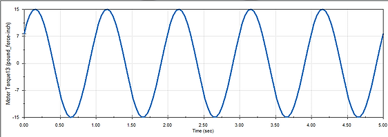
Figure 6 - SolidWorks torque analysis of the selected movement method

Figure 7 - SolidWorks finite elements stress analysis
Final Design
The final walking machine was constructed using laser cut plywood for the chassis, machined aluminum linkages and mounting brackets, and hardware from the provided kit of materials (bushings, bearings, gears, set screws, etc.).
Our design proved to be successful in completing the obstacles originally decided upon in the early design phase: the hard maze obstacle, the easy teeter-totter obstacle, the short peg forest obstacle, and bypassing the wall obstacle.
Unfortunately, during competition, the walking mechanism fell into an unexpected movement pattern shown in Figure 9. In testing the pattern did not occur but as components wore from use the machine became more prone to failure and gave out during competition.
Interestingly, through a failure analysis after the competition it was determined that had the machine been driven in the opposite direction, the failure would not have occurred. A more detailed description of the failure can be found in the report below.
ENGS 076 Final Report

Figure 8 - Final walking machine

Figure 9 - Bad movement pattern