
Walking Beast
ENGS 146: Computer-Aided Mechanical Engineering Design // Professor Solomon Diamond
Team: Amanda Roberts, Juhi Kalra, Latika Sridhar, Sophie Sheeline
Project Objective
In 5 weeks, design, test, and fabricate a pedal powered walking machine to compete against other machines in a class jousting competition.
The machine had be able to be driven by anyone between 5'5" and 6'3" and be capable of making a 180 degree turn within the game boundaries.
I was the lead engineer on developing the drive train system. I designed and fabricated of two forward and reverse transmissions based on a 3D SolidWorks model and FEA analyses on transmission components.

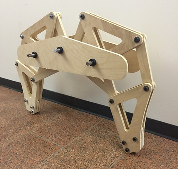
Figure 1 - The final walking beast
Design and Analysis
The project was broken into three modules: Chassis design, Leg design, and Drive Train design. Each member of the team was involved in the design of each module but two engineers had primary responsibility for the drive train, two for the leg design, and one for the chassis design. I was one of the two primary engineers on the Drive Train design team.
Leg Design
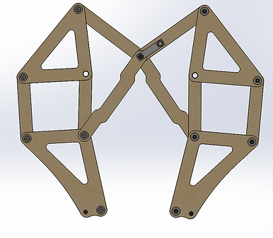
Two options were evaluated for the machine's leg design: the Amanda Ghassaei linkage and the Theo Jensen linkage.
The Jensen linkage was chosen due to its greater step height and faster speed per rotation of the crank.
Stress, motion, and torque analyses were performed to determine the number of leg pairs, their size, the design of the steel crank, and the torque needed from the driver.
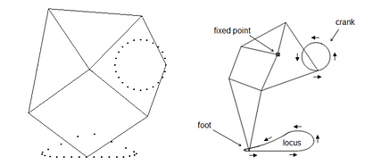
Figure 2 - Linkages considered for the walking beast. The Amanda Ghassaei linkage is shown in the left image and the Theo Jensen linkage is shown in the right image


Figure 3 - Motion analysis of a set of two Jensen linkages (left) and a set of three linkages (right). The set of three has virtually no time where a leg is not in contact with the ground producing a smoother path


Figure 4 - Torque analysis of the leg motion (left) was used to perform FEA analyses of the leg crank piece (right)
Drive Train Design
The drive train had to be able to to turn the machine and deliver the necessary torque to the legs to move both forward and backward.
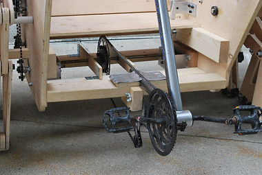
Two transmissions were built with forward and reverse gears to achieve a zero radius turn. Sprockets from old bicycles were used to increase torque from the pedals to the legs.
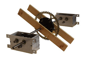
Figure 5 - Constructed transmission drivetrain with main input sprocket at center

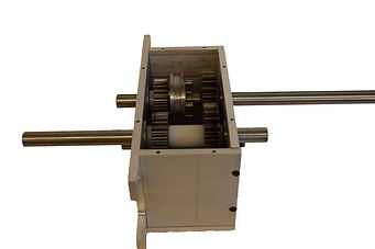
Figure 6 - SolidWorks model of a single transmission (left) and the fully constructed version (right). The dog gear is controlled by a lever pinned to the chassis. When pushed to the right or left the dog gear engages either the forward gear (3 stages) or the reverse gear (2 stages)
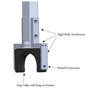

Figure 7 - SolidWorks model of the dog gear lever (left) and the fabricated version attached to a transmission (right). The lever design allows only lateral forces to be applied to the dog gear so that the gear does not twist off axis and bind to the shaft.


Figure 8 - SolidWorks model of a dog gear (left) and the FEA stress analysis (right). While it is more difficult to machine, steel was chosen over aluminum to withstand the forces from the drive shaft. Steel pins were press-fitted into the dog gear and engage with holes milled into the forward and reverse gears.
Chassis Design
The chassis was designed to accommodate a rider between 5'5" and 6'3", provide a stable enough structure to transfer the load from the rider to the legs, and provide mounting locations for the drive train.
The final chassis design included wooden mortice and tenon features to reduce the number of metal fixtures used during fabrication (i.e. screws, L-brackets, etc.). 2x4s were used to provide structural support in addition to the 0.75 and 0.5 inch used for the rest of the chassis. The plywood was cut to shape with a ShopBot routing machine.
The leg and drive train teams maintained continuous communication with the chassis designer so that all modules fit together as seamlessly as possible.

Figure 9 - SolidWorks rendering of the final assembly. Mortice and tenon features can be seen on the plywood pieces over the legs

Figure 10 - SolidWorks FEA stress analysis of a chassis wall. Green arrows denote the fixtures in place for each portion of the chassis connected to the center cockpit. The purple and orange arrows denote the forces acting on the wall.
Fabrication and Final Machine
Throughout the term each member of the team aided in the fabrication of the final modules using CNC mills and lathes, the ShopBot router to cut plywood for the legs and chassis, and hardware purchased from online vendors. Once each module was finished the full machine was assembled into its final form.
Leg Assembly
Drivetrain Assembly

Completed Walking Beast
